Tandy 1110HD Laptop - Spelunking Through 16-bit Assembly
The Tandy 1110HD
I recently came into possession of an old Tandy 1110HD Laptop, a early 90s era machine with a V.20 cpu, the classic 640k of RAM, a CGA class monochrome reflective LCD display, 720k floppy drive, and a 20mb Conner CP-2024 hard drive. I grew up around a Radio Shack franchise and actually had one of these machines a very long time ago. I’m reasonably comfortable around a soldering iron and test equipment so when I found a couple of these being sold for parts on Ebay, I decided what the heck and picked them both up.
There are a couple of known issues with this particular machine that I was aware of going into to things:
- The floppy drives fail due to a rotted belt, usually this is correctable with an appropriate replacement.
- The Conner CP-2024 hard drive is known to fail due to a rubber bumper inside the drive that degrades and eventually leads to the head being locked in the parked position.
- The machine uses a 2.5" XTA drive (aka 8bit IDE) that is incompatible with ATA IDE (16bit) and has very specific bios enforced limits on what drives it can use.
- All of the internal drives, including the floppy drive, use special non-standard connectors and FFC or Flat Flex cables to connect to the main board.
The machines I found online did not have a power brick with them, though that was the easiest thing to fix. The 1110HD uses a 9.5v 2.1amp supply with a negative center on the barrel connector. Amazon sells a number of usable 9v supplies in about the right range and amperage. Since I know that battery on this thing is a goner, and almost all of the logic is 5v or less, and it has no backlight, that extra .5v isn’t going to matter too much. The only annoying part was watching out for the connector polarity and size.
Once I had both machines and the power supply, I tried powering the up, just to see what I had before going too far. With hardware this old, there could be any number of things wrong for leaky batteries to bad caps that literally started dissolving the motherboard. Surprisingly, both of them powered up on the first try. Both floppies were dead of course, I could hear the remains of their drive belts flopping around inside. One of my pair even had a still functioning hard drive. No issues with keyboards or displays.
In some respects, I’d lucked out.
Tear Down and Cleaning
I picked the better looking of the two machines and started pulling it apart. This proved pretty straight forward with one notable exception. There are covers over both of the LCD hinges that are kind of tricky to pull off. They hook in the front and you have pull them up and forward to get them to unlatch. I’m kind of surprised I didn’t break them.
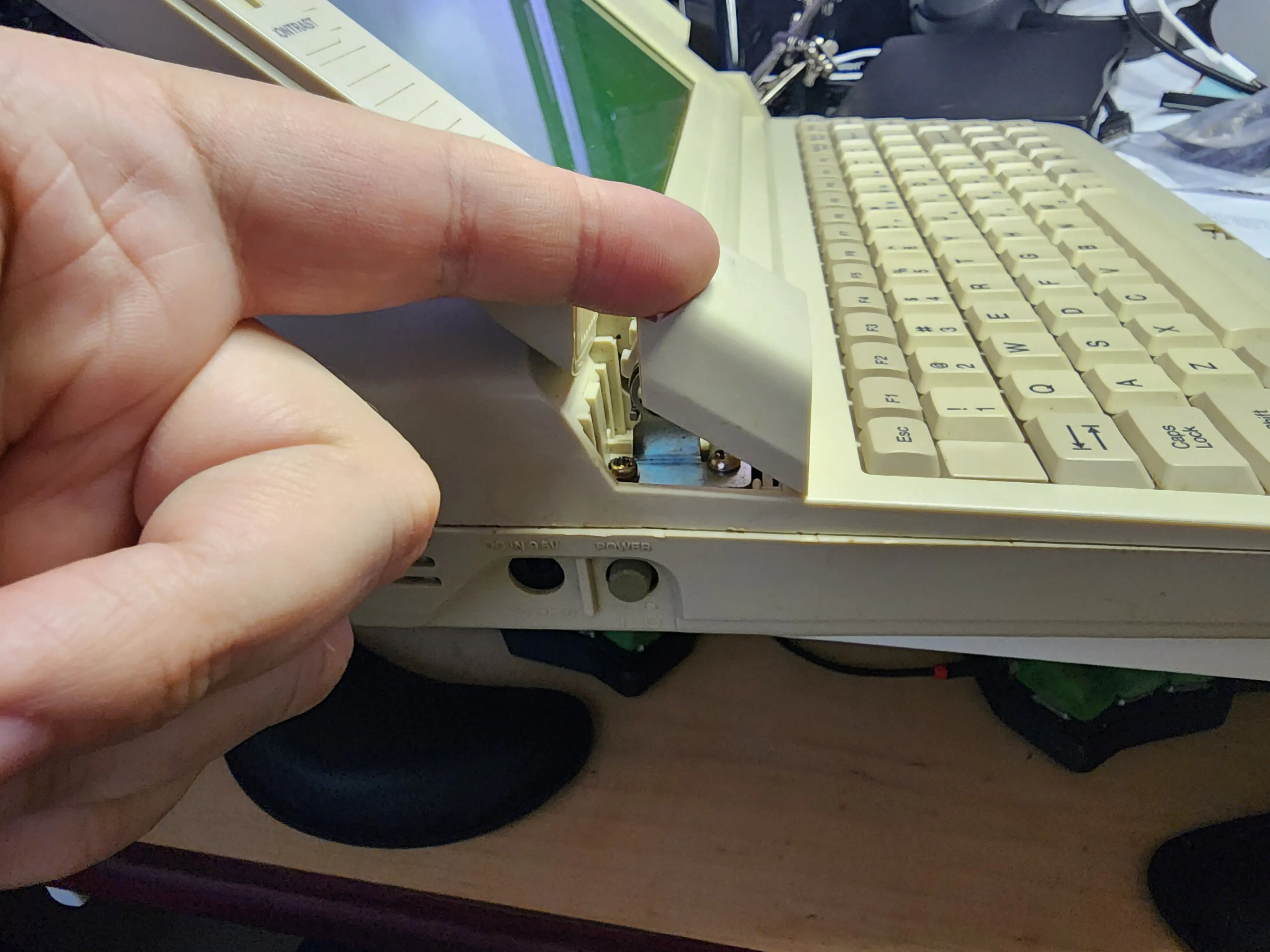
Partially removed hinge cover.
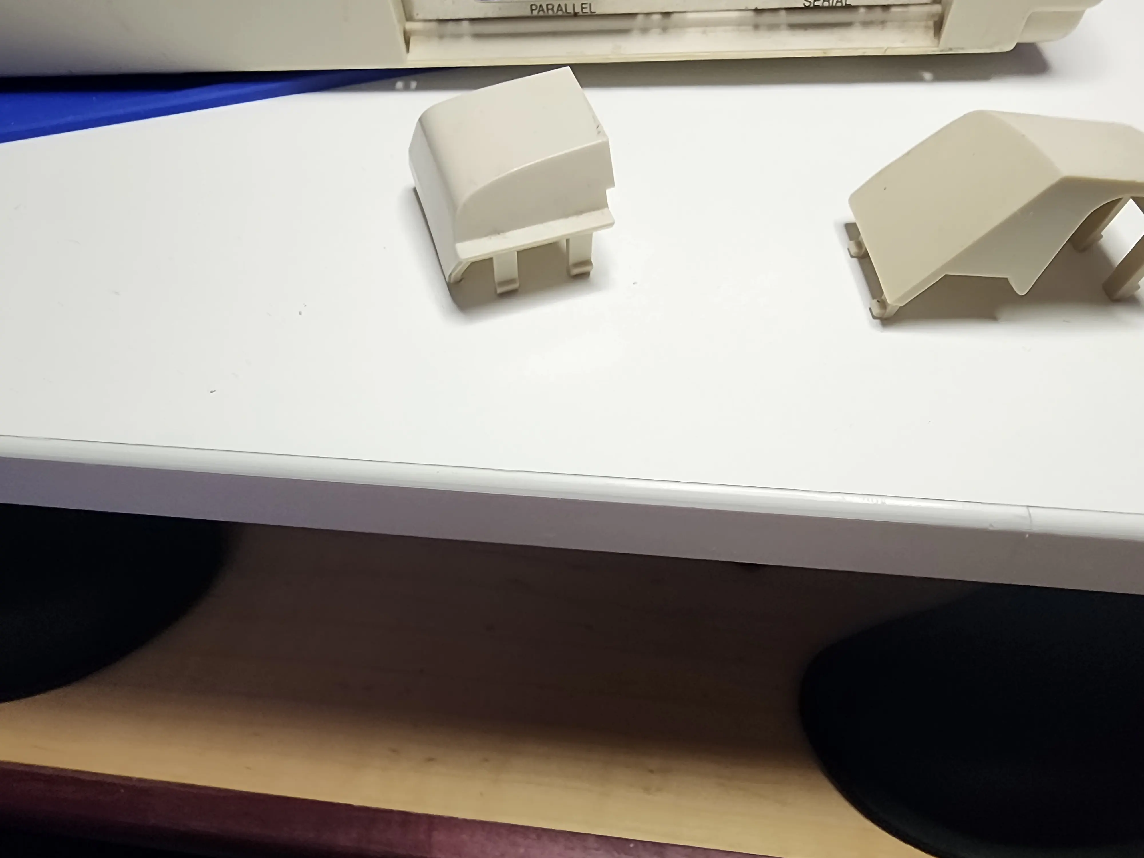
Fully removed hinge cover front and back side.
The covers are not interchangeable and have deeper “hooks” on the front edge. The clips on the back edge have to give way to remove them and to reinstall them, you have to hook the front first. After that, there there two screws on each side for a total of four holding the LCD to the machine. You only really need to remove the front screw on each side to remove the top, the one that’s in the L portion of the hinge bracket. That’s what I’d recommend doing unless you’re going for a complete disassembly for retro-brighting or similar.
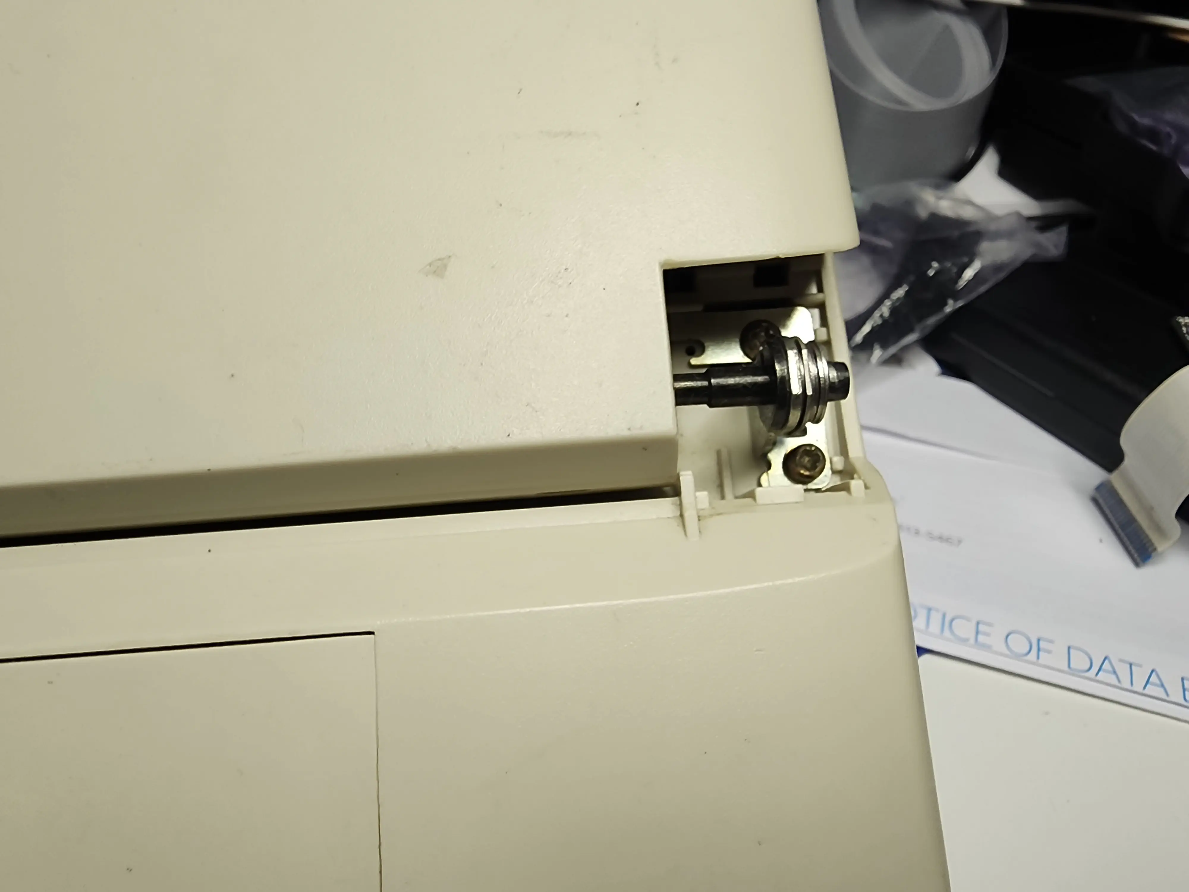
Detail of LCD hinge screws. Front of the laptop is to the top of the image.
From there, you have basically two types of screws:
- Machine screws that go into threaded inserts of metal.
- Coarse threaded screws that go into plastic.
With very few and obvious exceptions, all of the screws fall into one of those two categories. There are no covered screws on the body of the laptop itself, though there are a few in the battery compartment. From there, It’s just pulling screws and the occasional snap together part.
Do keep an eye out for FFC (those plastic ribbon cables) for the keyboard and floppy drive. You pretty much have to completely disassemble the machine to get the floppy out without risking breaking something. I believe it’s better to try removing the hard drive and motherboard first before attempting to remove the floppy. The hard drive mounts share screws with the floppy and I believe they are usually on top of the floppy mount. The floppy faceplate is actually part of the case, and the eject button captures the drive between the case and an internal metal shield under the motherboard. Otherwise, it’s a pretty straightforward tear down job, you just have to go deeper than I would have preferred.
Floppy Drives
The floppy drives are annoying. They have a drive belt that’s tricky to find and use a 24pin FFC cable rather than the more traditional 34pin ribbon and separate power cable. Thankfully, I was able to find an adapter after a bit of digging. It seems that Korg used either the same or a very similar drive in on of their (I think) midi keyboards. I picked up a pair of these adapters.
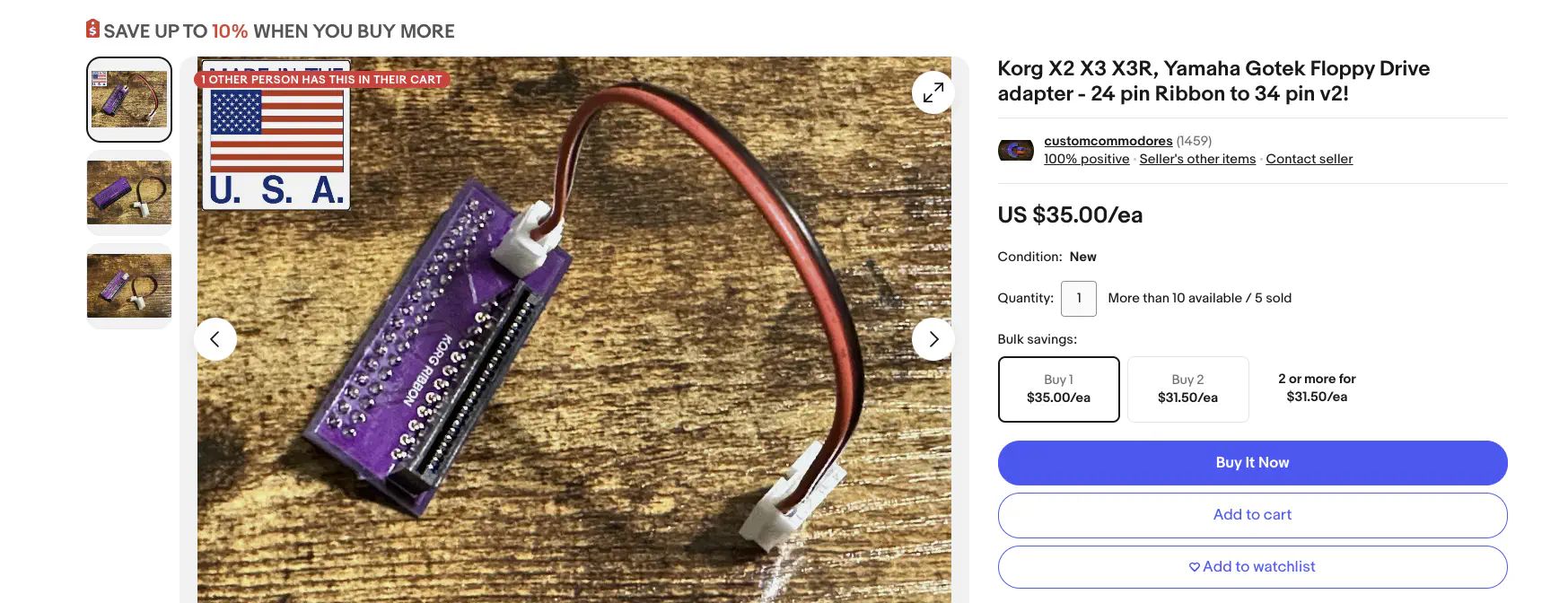
Korg X2 X3 X3R Yamaha Gotek Floppy Drive adapter.
Hopefully that will still be live for whoever needs it. I couldn’t get this to work with a real drive, and I couldn’t get the original drives working again, even with a replacement belt. I’m still not sure what’s wrong with them. The adapter worked beautifully with a Gotek though. Just pick one of the nicer ones and flash it with FlashFloppy if it doesn’t come that way. This worked beautifully with a tiny flash drive.
Since the face plate is part of the case, the plastic body the Goteks come with wont really work in the 1110HD. Thankfully, there’s nothing structural about that plastic body and it’s easy to remove. It was either pull the Gotek board or cut into the Tandy’s case and that would likely have compromised it’s structure. So, pull the Gotek board it was. There are some small plastic pillars in the drive bay that look like they might have been used in the molding process or to make sure the floppy drive is physically aligned with the case that were in the way. I felt it was reasonable to clip these since removing them would not compromise the case’s integrity and I couldn’t mount the Gotek board flat with them in place.
Since this puts all of the Gotek’s controls inside the case, and hard to get to, I used a couple of Choc key switches I had laying around to build an extension board to mount in the modem slot on the back. Eventually, I’ll replace this with a 3d printed part that takes up the whole slot, includes the LED panel (or an OLED display) and has an extension for the USB connector.
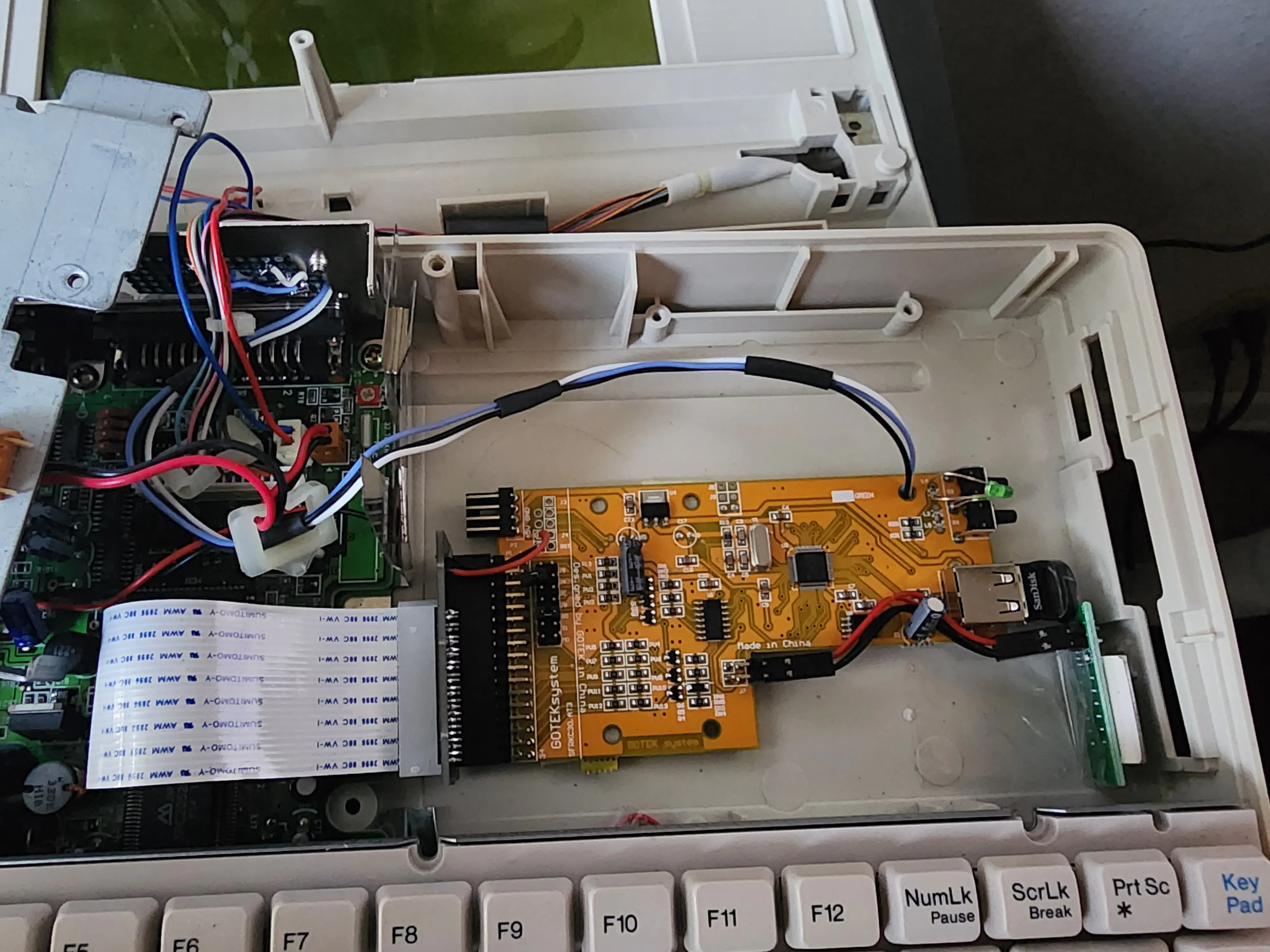
Temporary Gotek install.
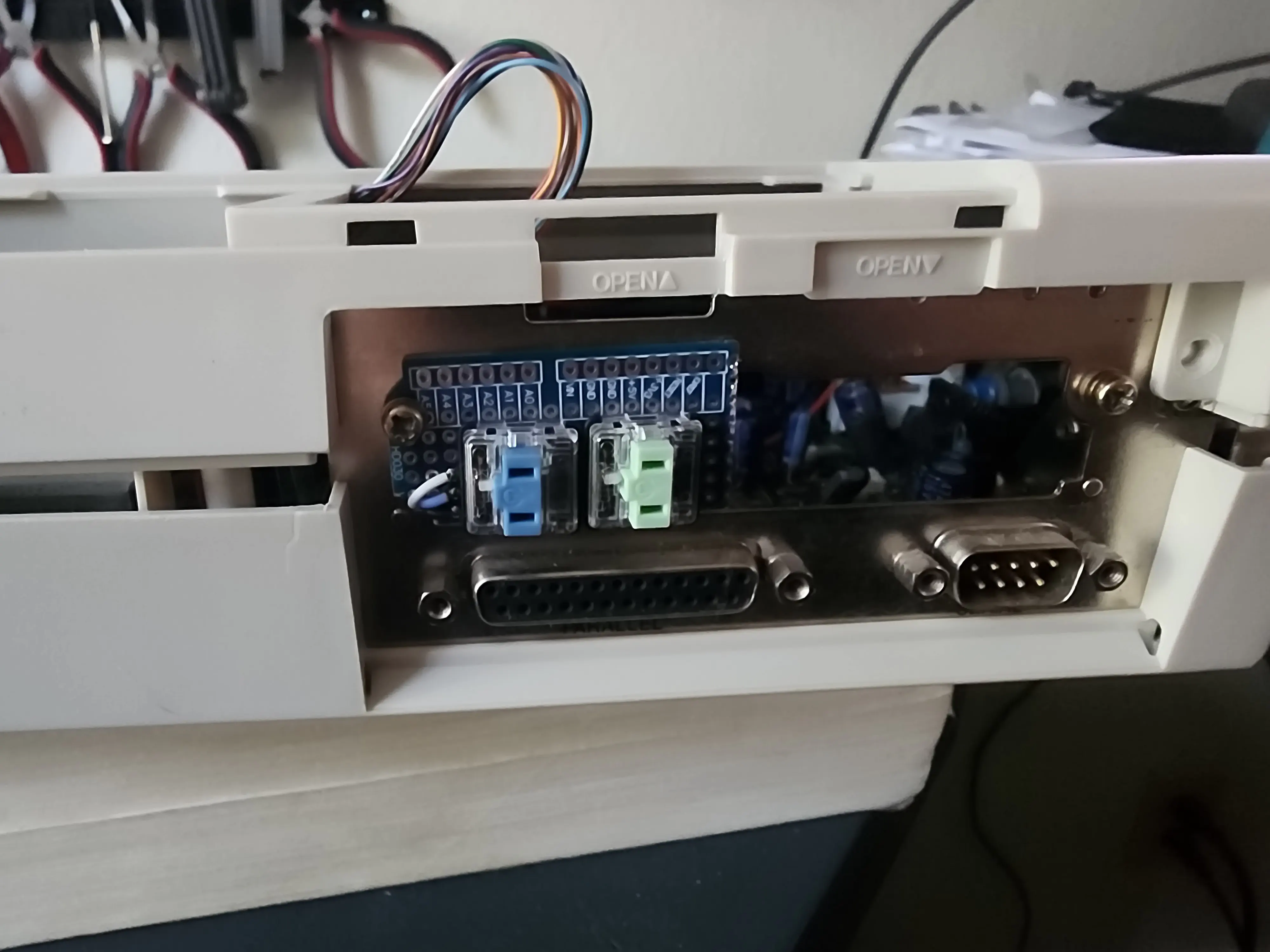
Goteck button extension board.
You do need to retain the frame that was used to mount the original floppy drive. The keyboard mounts to that frame and removing it would leave the center of the keyboard effectively unsupported. For the temporary install, I’m using a bit of double stick tape, but I’ll probably replace that with 3M Dual Lock (i.e. really strong velcro) before I button this thing up again.
XTA2SD
So, I’ve got the machine booting but only one working hard drive and that drive is suspect simply because of its age. Time to look for an alternative. If this were a slightly newer machine, I could probably replace the drive with a CF card and an adapter board. Unfortunately, the bios in these machines is extremely picky about the drive that’s installed, only supporting a small number of sizes, and doesn’t support ATA at all. You can get a feel for some of the differences in this video, this blog post, and/or taking a look at a comparison here. Basically, you’re not going to get an ATA drive working on an XTA interface and not going to get an XTA drive working on standard ATA IDE.
The XTA protocol itself is extremely under documented, almost to the point of there being no documentation. The PC XT technical referenced has some documentation and if you look up data sheets on the controller ICs (the Conner CP-2024 use s Cirrus Logic CL-SH260 and there’s a Western Digital WD1002S-WX2 that I’ve seen data sheets for online) you can find some documentation.
The jackpot for me was finding this thread over on VCFed. Turns out there’s at a couple of people working through building a replacement for these drives. The thread starts out talking about a drive replacement and possibly a controller replacement and that runs for along for a year until a user named Callin Elvis picks things up again.
And then we have this:
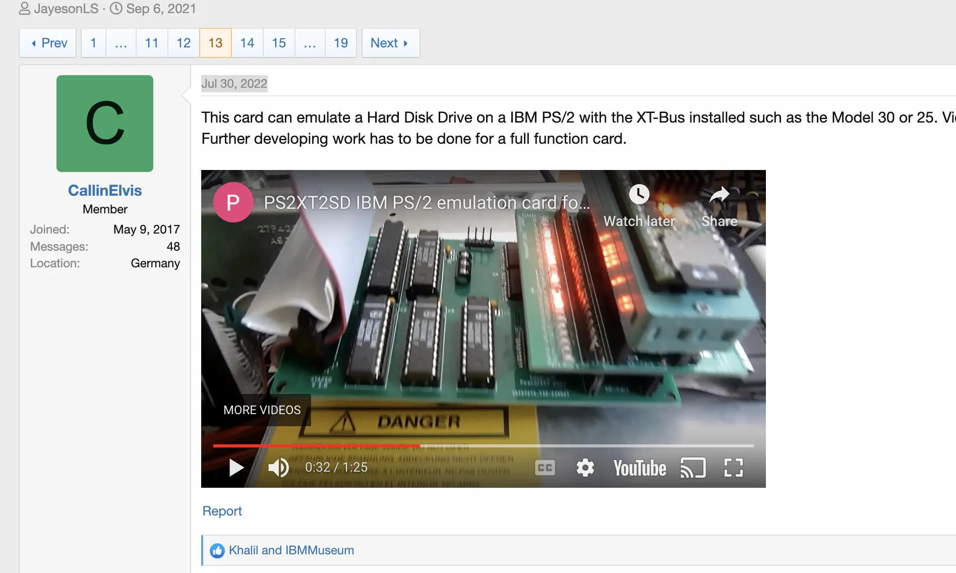
Screen shot of post about PS/2 machine booting from XTA2SD prototype.
That post is followed by several more covering different machines showing different iterations of the card. Unfortunately, no one was able to get it working with at Tandy 1110HD in the thread. Still, it seemed promising and there was enough information to work with. The Tandy 1110HD has a socketed BIOS ROM, so I could easily pull it and start mucking around in the code if I needed to. So I contacted Callin on the forum and purchased one of his prototypes to give a try.
Failure
It took a couple of week or so to get the drive to me from Germany and then another several weeks to the acquire the 44pin in the right pitch, ribbon cable, and 40pin connector I needed to make an adapter cable for it. The Tandy 1110HD has a 2.0mm pitch 44pin connector that includes power for a 2.5" hard drive while the XTA2SD card uses a more common 40pin 2.5mm pitch connector that you’d find on a 3.5" drive. I also had to track down a crimp tool for the IDC (Insulation Displacement Connector) style connector.
The 44pin side was easy, just align and crimp. Since the 40pin side used a different pitch, it was much trickier. Not hard, so much as really, really annoying. I had to separate each conductor one by one and make sure there was enough slack to work with. Then push each individual conductor down on to the connector one at a time. Then extend one pin for 5V power. Thankfully the first 40 pins were straight through.
I put the XTA2SD board in the machine, powered it on, and after about three minutes had “Hard drive initialization failure” pop up on the screen. Of course it wouldn’t be that easy.
What’s Next?
I did eventually get this thing booting off the internal drive. But it took a bit of BIOS patching and is very very experimental. Did I mention that I had two of these machines? Well, one of them is on its way to Germany and Callin Elvis as I’m writing this. It’s sitting in the Chicago Illinois International Distribution Center right now. I included the working drive, hopefully it survives shipping, so Callin has something to compare to.
I plan to do a follow up here and dig more into what the BIOS is actually doing under the hood to see if I can figure out why it doesn’t like the XTA2SD card and potentially see if I can get my machine to allow a slightly larger HD size (20mb is just too small).
If I can get this working, I might look into finding and Tandy 1000 HX machine. I grew up with an EX and the HX is a variant that included a hard drive and 720k floppy instead of the single 360k drive. Though that would require a dedicated place to set the machine up and a replacement for the old CRT display.
I’m also thinking about battery replacements for the Tandy 1110HD. It’s likely that the 9.5v supply is mostly to allow for charging the 6v sealed lead acid battery the machine came with. In theory, there should be a means to adapt a modern powerbank to fit the internal power socket and power the machine. In theory.
Till next time.