Tandy 1110hd Replacing the Battery
Old Batteries
It’s been a while since the last time I worked on my Tandy 1110hd partly because of normal life and partly because I’ve been playing around with another project. I was able to get my hands on a pair of Compaq Portables in reasonably decent shape. Thankfully, both units powered on (classic buy two in questionable condition to make one working unit) and neither has suffered the exploding tantalum plague so I got lucky again. But we’re here to talk about a Tandy not a Compaq.
One of my goals for the Tandy has been to actually make it portable again. The original sealed lead acid batteries are basically unobtainum from what I’ve been able to discover. At least if you want them to fit into the same space as the original batteries that is. Interestingly it’s almost perfectly sized for a 2S 18650 lithium ion pack. You could probably find li-poly packs that would fit as well if you really wanted. But I started with an inexpensive 18650 pack from amazon in about the right milliamp hour rating for this experiment. If you have bare cells and need to solder things, li-poly’s would be better overall, but they aren’t as physically durable and you’ll have to find the right dimensions, which might be harder to do in that form factor.
Voltages
Now, the old lead acid pack is rated at 6v and our hypothetical li-ion pack will have a nominal voltage of 8.4v give or take a bit. Anecdotally, I’ve seen evidence that the difference doesn’t matter here. From my own testing in a Tandy 1100fd (fd not hd) that has a busted screen, the Reddit poster seems to be correct. Really, that makes sense overall. The stock power supply for these machines is a 9.5v 2.1A power brick. Internally, the battery is routed to the power switch through almost the same traces as the power supply connector and all of the regulation seems to happen down stream of that switch.
The one problem is the old charging circuit. This one took me a while to figure out a solution for. The old sealed lead acid battery is pretty simple to charge, wire it up to a voltage source and let it run. From what I can tell, there’s a J220 P-channel mosfet on the mainboard that handles this. It’s wired up to pass battery voltage into the system and when unpowered and produce roughly 7 volts when the power brick is connected. It’s not a regulated 7v though, there’s a simple voltage divider on the back side of the main board biasing the gate fo the mosfet at just the right level to get that 7v. At least that’s what it looks like from what I can see. So, when plugged in, there’s a constant 7v fed to the battery terminals and otherwise, the battery is dumping its output into into the mainboard.
For a sealed lead acid, that’s fine, not so much for li-ion cells. The 7v is well below the charging voltage for a 2s li-ion pack, but you don’t charge li-ion’s with a continuous trickle charge. They need a more specialized charging curve. Thankfully, I have voltage to spare since the upper end of the new pack is well above old batteries max. So a diode should do the trick to keep that 7v from accidentally overcharging the new pack.
Isolating the Battery During Charging
That still leaves the need for a charging circuit. Li-ion packs need a specialized charge controller and extra load on the controller can mess up the charge curve. This is a pretty common problem when building DIY charging circuits. If you don’t isolate the battery from the load before charging, you wind up with the load in circuit and it throws off the charging curve enough to potentially damage the batteries or worse. Not a mistake I want to make.
The other thing I wanted to avoid was needing a separate connector to charge the battery. It would be simple enough to do, but then I’d need a charger and separate power supply to power the laptop and have to remember to connect them in the right order etc. This needs something more than a diode to solve.
That’s where this little setup comes in.
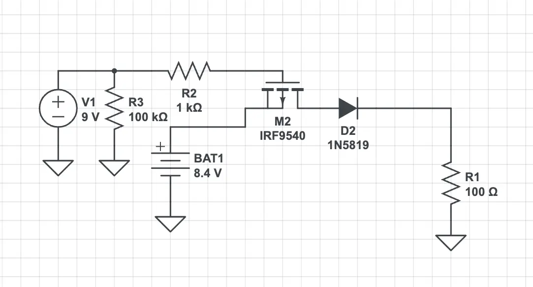
Prototype battery 'isolation' circuit.
I used Circuit Lab to prototype and simulate the circuit before ordering the parts. R1 in the diagram represents the laptop as a load. D2 (there’s only one in the diagram, the numbering is out of sync due to me messing around) is there to prevent the aforementioned 7v trickle charge from causing problems. Since this is prototype, and I’m not designing a board, this is all through hole stuff and way over engineered. The 1N5819 is a 40V 1A schottky diode and what was available in Circuit Lab to simulate. What I actually used is a 1N5820 which is a 20V 3A Schottky. Either will likely work, though you probably want the higher rated diode if you keep the mechanical floppy and have a working mechanical hard drive. The drop on mine is about 0.16~0.17v which shouldn’t pose any problems.
The IRF9540 is a P-channel power mosfet. It needs to be a P-channel mosfet because I needed a postive voltage on the gate to turn the mosfet off instead of on as an N-channel mosfet would have. To be fair, my general electronics knowledge is minimal, so it’s entirely possible I have this wrong, but it works. The voltage divider ensures that the gate is pulled back to ground when the external 9v supply is not present and not floating randomly. Note the direction of the body diode as well. The laptop is on the drain and our battery his connected to the source to avoid accidentally dumping current through the body diode instead of the channel of the mosfet.
With this setup, you get battery voltage at the output of D2 when the gate is unpowered and nothing when it is. There’s enough capacitance in the laptop and this circuit switches fast enough that we don’t have to worry about a brown out when plugging in or disconnecting the charger.
All of these parts were readily available form Digikey along with a heatsink kit for the TO-220 packaged mosfet. Since I’m not building a board for this version, I used a bit of prototype board I had on hand and some creative “air” wiring to put my little isolation circuit together.
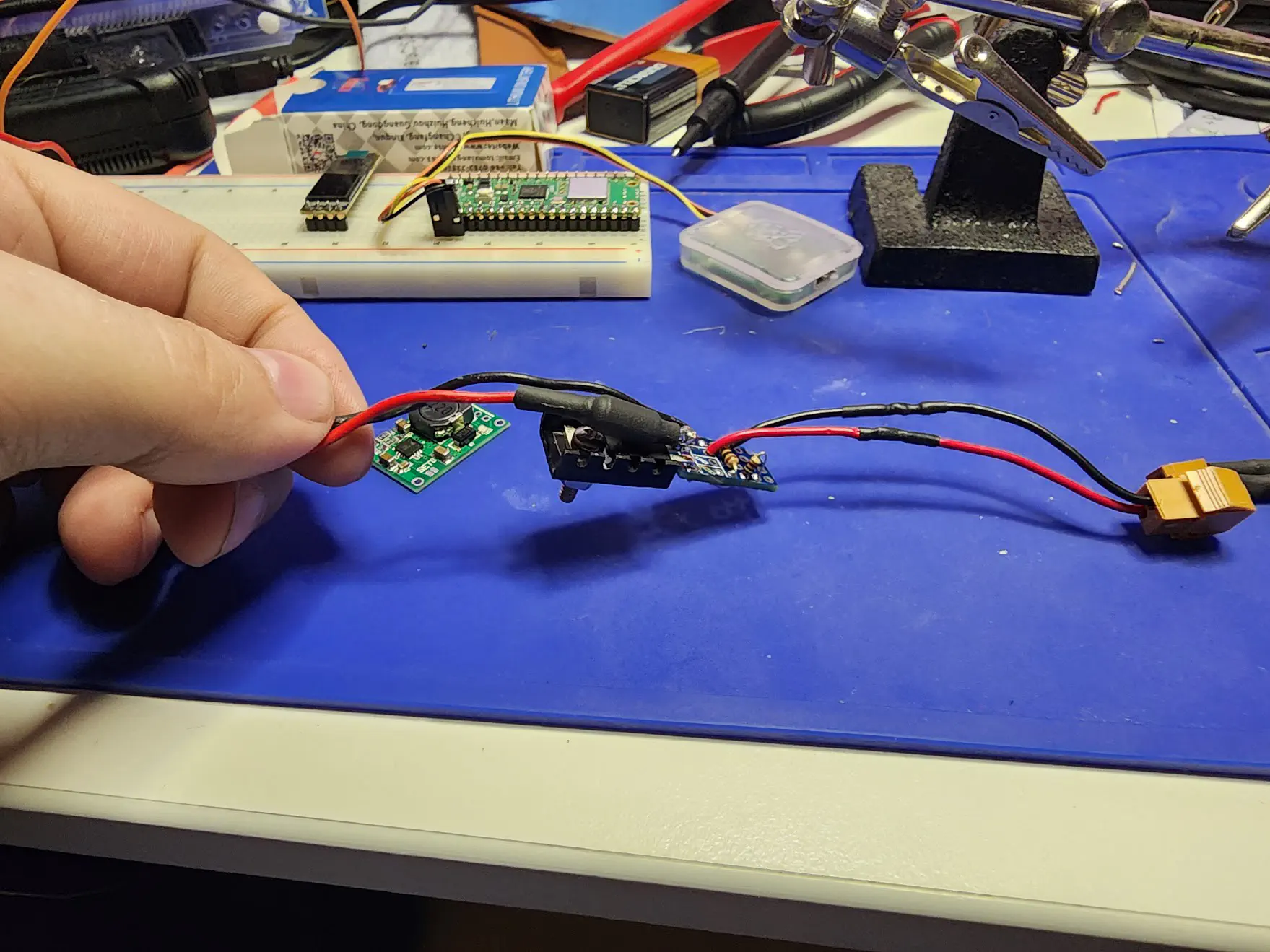
Partially assembled battery adapter
On the laptop, there’s a 3~4 inch jumper wire between the battery connector that’s mounted on the floppy drive frame and the main board. It has the same connector as the original battery on the mainboard end and a similar female connector on the other. I preserved the old connectors to make things simpler, though you could easily change out the one on the battery side if you wanted. I’m still not sure what kind of connector it actually is.
Charging Circuits
As stated above, li-ion packs need a specialized charger and you really want a pack with protection circuits. Completely discharging a li-ion pack (i.e. all the way to 0v) will damage the pack to the point it’s likely unrecoverable, at least without specialized equipment. Protection circuits generally have low voltage cut-outs to prevent you from damaging the pack so you really really want a pack with them or to add them. Good protection circuits should also provide at least some degree of balancing between the cells.
This machine needs 5v to run the logic and the old pack was a 6v battery, we either need a 1s pack and a boost circuit or a 2s pack (we already know the machine can tolerate the higher voltage so we shouldn’t need to regulate it down). A boost circuit adds more complexity and a continuous drain on the pack, so avoiding that is extremely useful. So, a 2s pack it is. Classically, a TP4056 or equivalent is an acceptable 1s charge controller, there are a number boards with this chip available on Amazon/AliExpress etc. But we need a 2s, not 1s, charger. For that, we need a TP5100 or equivalent.
Thankfully, these are cheap and ubiquitous on through the aforementioned usual suspects. The one caveat I’ve run into is that at least some listings have the SET jumper defined backwards. If your board produces a 4v charging voltage instead of the expected 8v or so, you probably need to short that jumper.
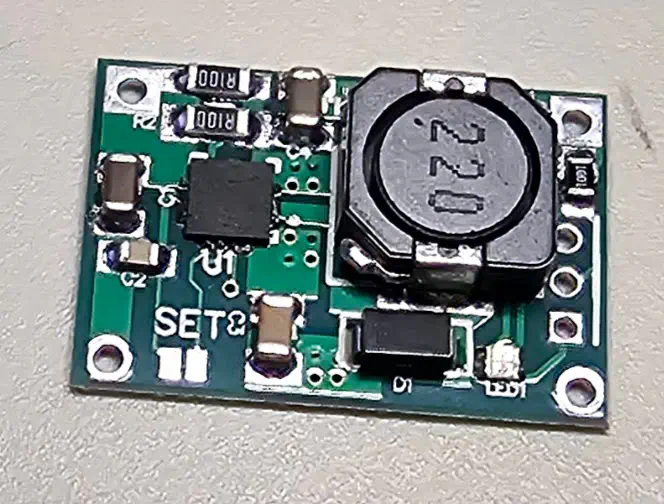
TP5100 charging board.
Unfortunately, I forgot to take a good shot of the final assembly before heat-shrinking the whole thing. I used a spare 1N5820 on the positive output of the charger since I’m keeping it permanently in circuit and wired it directly to the battery leads. Be careful of your wire gauge feeding into the charger, I hunted up some 18 gauge wire based, probably too much, since all I had was 24 gauge (good enough for the control signal but not the charging current). Thankfully, the ground side of the charger board is just a continuous plane, so the you can directly connect the ground side of the battery leads to the charger and straight to the connector going into the mainboard.
Powering the Charging Circuit
Input power is a little tricky though. My first attempt was to wire to the input lead to unswitched side of the power switch on the main board. This … didn’t work. It took me way to long to realize that connecting the battery was feeding that side of the power switch and inadvertently powering the charging circuit off the battery. Again, this would create a phantom load and kill the battery. So I did a little digging and figured out where the power connector feed into the system. I haven’t traced out the entire circuit, but I did find one spot on the inside of a fused link that connects to the external power connector and not directly to the power switch or battery. It seems to be upstream of the old lead acid trickle charger.'
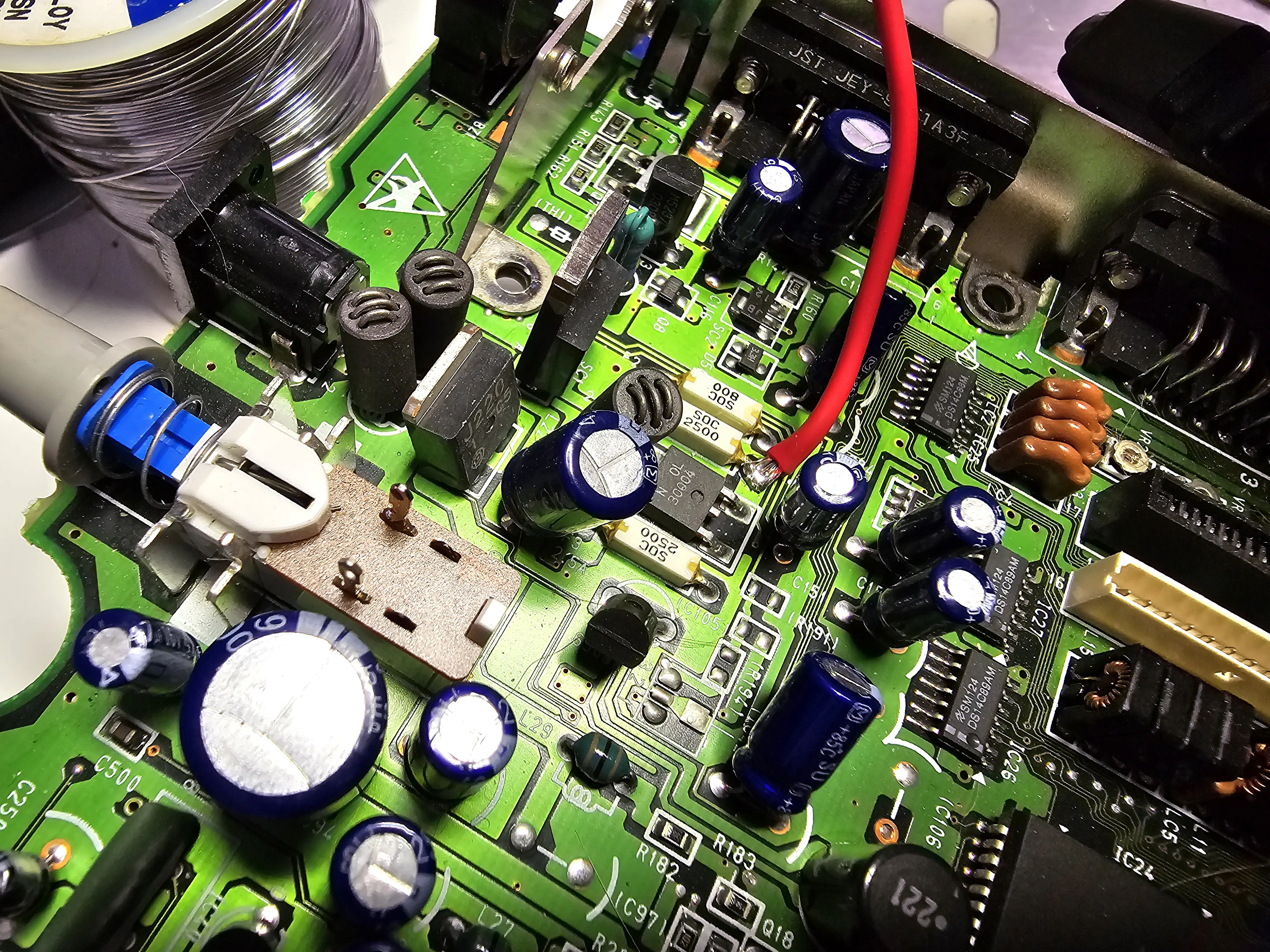
Where I tapped into the raw power brick feed.
There are three white fuses on the board, this one is on the power jack and has an almost direct line back to it. The only thing between that point and the jack is the fuse, traces, and whatever those ferrite/inductor things are. I suspect they’re filtering of some kind. I thought about pulling the J220 mosfet but that was getting more invasive than I wanted and I’m not sure it would help. I’d still need a switching circuit of some kind of choose between charging and discharging the battery etc. I’m also not sure what the TO-263 packaged chip is next to the fuse. It does appear to provide some degree of isolation between the input jack and switch though.
I don’t particularly like the solder joint on the fuse, but it appears to work and there shouldn’t be a lot of mechanical load on it. For now, I’ve added jumpers to the charger board that should let me add status LEDs externally later, but I’m relying on the on board LED to tell me when it’s done charging. If you’re careful routing the leads, there’s plenty of room in that part of the laptops case for the isolation circuit and charger board. I redid the heatshrink on one of my packs, because I wanted to make sure there were protection circuits on it, but that’s not necessary if you’re careful to leave plenty of lead when replacing the connector.
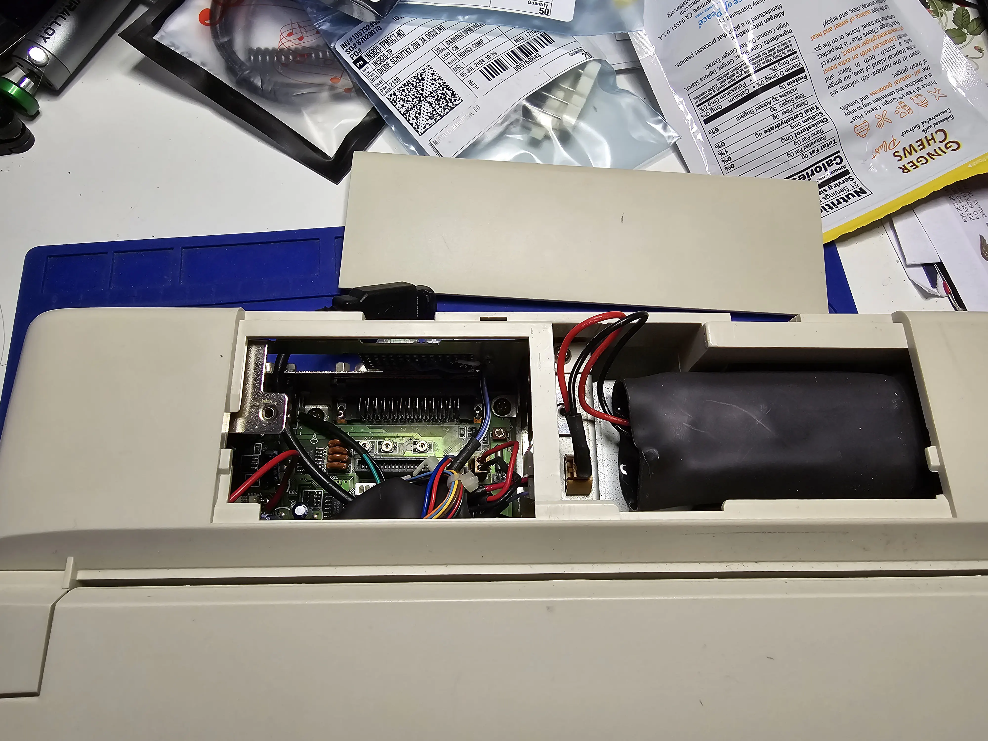
Battery and charging circuit in situ.
So far, I’ve charged the battery but I haven’t done a fill discharge on it. The pack is a 3000mah 2s one I found on Amazon pretty cheaply. It’s probably not the highest quality, but does seem to be enough to power on the laptop for the short times I’ve tested. Now that I have charging figured out, it’s time to do some more extended testing and see just how well it actually works.