Tandy 1400 HD/FD PSU Replacement
The Tandy 1400 HD/FD
Well, I’ve gone and purchased another set of old Tandy laptop machines that only half function. At least, only half functioned when they arrived. This particular machine is a bit of an annoying one to work on and one that has defeated some loftier heads than mine. Well, perhaps not quite defeated, but definitely not the most successful. (I still kind of wonder what happened to that machine …)
My particular specimens include two Tandy 1400 FD machines and one HD machine in various states of repair. Internally, they are almost identical with only slightly different ROM versions and differing drive configurations. Both models have the same board layout and internal pin-outs, etc. I don’t have an LT model machine and I’ve been lead to believe that it is very different internally including a different PSU, different voltage rails for the LCD, and a different input voltage. That, unfortunately, means that results of my little side project likely won’t work for that machine but it does seem to function pretty well in the HD and FD variants.
If you come across these machines on E-Bay or what ever local auction site you frequent, they almost universally “power on” but don’t boot. You’ll see a blank screen with flashing low-batt light and probably all three “lock” LEDs light. At least all three of the units I have showed these symptoms. Don’t worry, the guts of the machine itself (the main board etc) are probably just fine, it’s the pesky PSU that has succumbed to the capacitor plague, potentially fatally. Either that, or you’ll find the machine doesn’t power on at all. If you’ve verified that the power brick is actually outputting the right voltage, there’s a high probability that the PSU board has blown its fuses on top of corroding away under the caustic guts of its capacitors.
When I’ve pulled these machines apart, there’s one particular brand, Rubicon, that I’ve found to have almost universally failed. I’d almost argue that the every one to these should be replaced on sight. The other through hole caps, mostly on the main board, seem to be OK. At least I haven’t had to replace them. The Rubicons though, yeah, all of them died and spewed their guts all over the place. Thankfully, it looks like there are only two of these on the main board with several other branded caps that seem to hold up. That said, you should check all of the caps on you’re boards just to make sure.
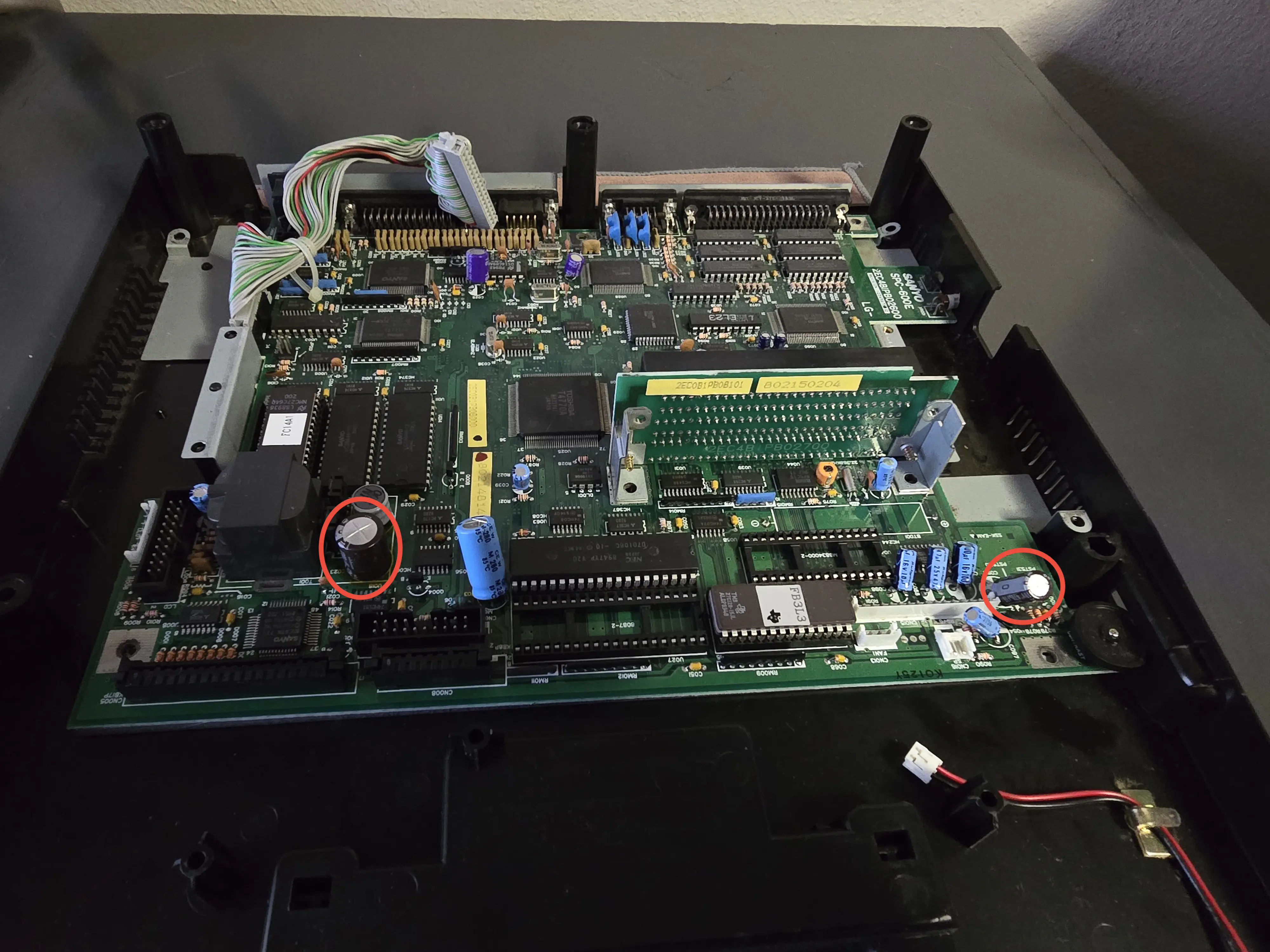
Main board problem capacitors.
I’ve circled the two that are almost guaranteed to be bad and leaking. There’s also a 3.6v 45maH NiMH soldered to the board next to the expansion backplane. (I’ve already removed it in this shot). It should be removed and/or replaced as a matter of course. I have yet to see one that’s leaked but there’s almost no way that battery is still good after all these years.
The PSU and Its Daughter Card
The PSU comes as a custom built, shielded module with an attached daughter card. The daughter card appears to be another 5v switching regulator that is fed off the main PSU, I’m still not quite certain of the logic behind it. There does appear to be some functionality to have an always on 5v rail that runs off the battery, though I’m not really sure what the machine does with it. The daughter card is mounted on the opposite side of the metal bracket that supports the expansion slot and loops back into the 15 position JST-EHR connector Tracking down exactly which connector this was took a while, thankfully it’s still made.
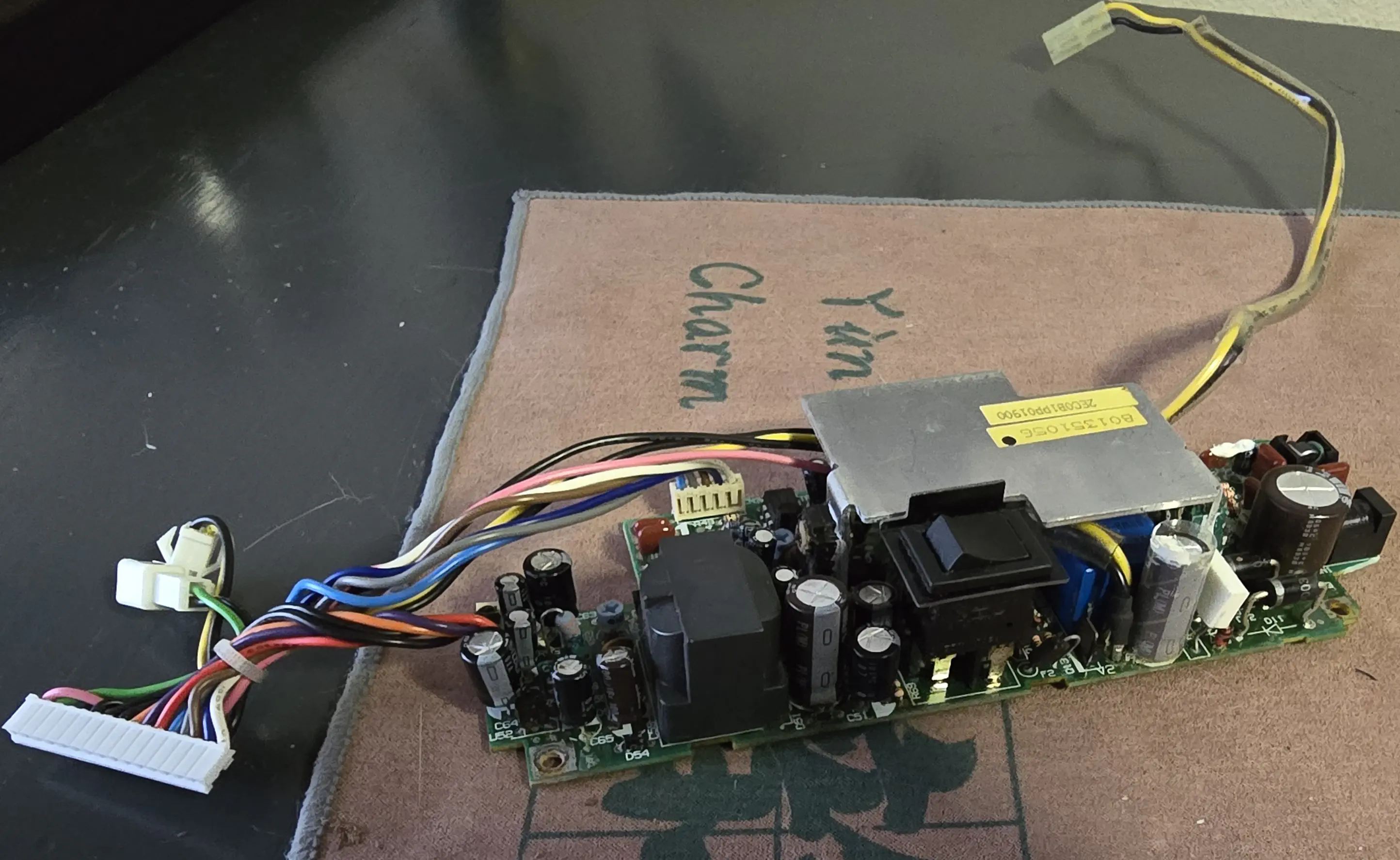
Original PSU board, decased.
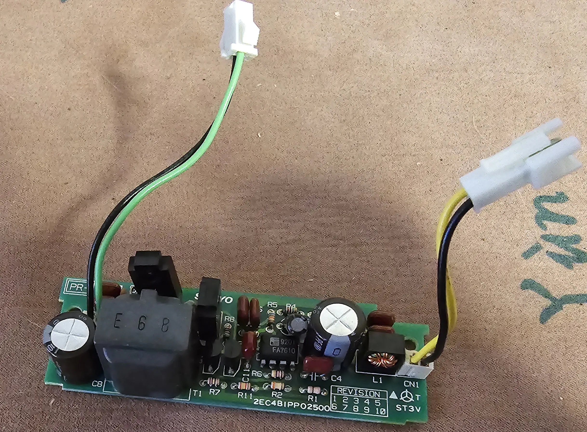
PSU daughter card.
You can’t tell much looking at the board on its own like that, but one glance at the shield and you get much better idea of what’s going on here.
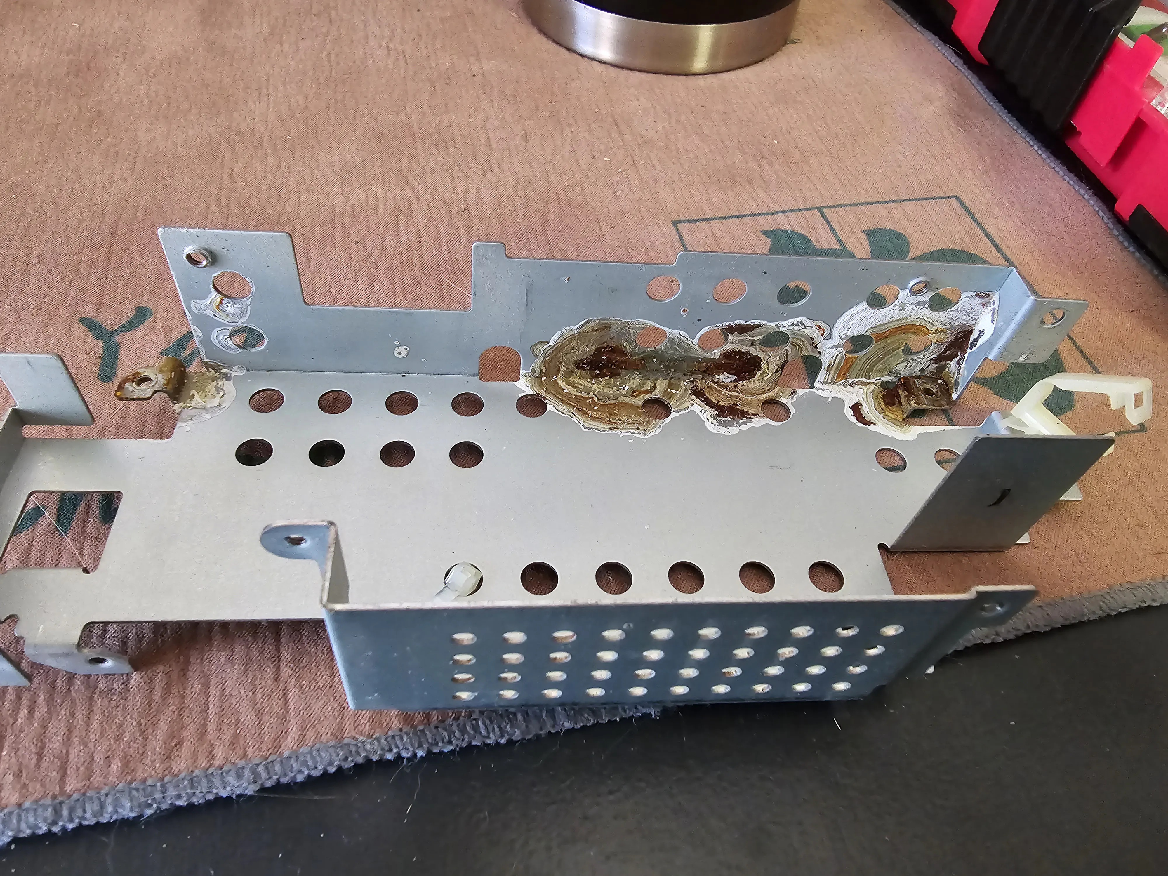
PSU carnage.
Yeah, that’s the same stuff that’s leaking all over the board, slowly eating away at it. If you’re lucky, it hasn’t blown the fuses or the MOSFET pack yet. It is possible to recover these boards with some work. I’ve brought one back to life with a number of Digikey orders, a lot of cotton swabs, some vinegar, isopropyl alcohol, and a bit of DeoxIT. Took several hours and then I had to go back through and manually re-adjust all of the voltage rails back to their expected values. The Lo-Tech wiki has a reasonable rundown of the voltages expected on the 15 pin connector. What it does not have is the signal lines and other things fed from the main board back into the PSU. If you look around on the VCF forum, there are a couple of threads where people were trying to reverse engineer the PSU to get a diagram and had slightly more detailed break downs of what the lines on that connector were as well as which ones were fed from the PSU to the mainboard and which ones were driven on the mainboard instead. I compiled my findings in a google sheet with links back to the original sources as best I could.
I’m not fully sure of all of the signal lines, though I do know that pings 1 and 2 are the two stages of low battery indication. Grounding them will get stop the laptop from indicating low battery and beeping at you continuously. Pins 12 and 14 come from the daughter card and are fed off a separate two wire connector from the PSU. The inputs and outputs are color matched: yellow to yellow and green to green. There’s also about a foot long lead over to the battery compartment on the other side of the laptop. The original battery is a big 4.8v NiCad pack which was long dead in my specimens.
Bringing the Machines Back to Life
As I stated, I did get one of these PSUs to come back and that was enough for me to get the rest of that machine functional. Though it would likely never be portable again and I don’t know how much I trust that PSU. The units were basically hopeless. I’m 90% certain one of them has a dead MOSFET pack that I’m not going to be able to replace and it’s blown almost all of the fuses on the board (there are at least two and I think there’s a third) which does not bode well for the rest of the electronics. Since I have one working unit, and the other one is in such bad shape, it’s not exactly worth it to restore the other PSU card.
But that doesn’t mean that all hope is lost.
There are a number of modern, switching modules available with either fixed or adjustable voltages in the ranges this machine needs. -22 is a bit of a problem, but the others are pretty straight forward. Knocking up a prototype using some cheap modules from Amazon turned out to be relatively easy, if a bit scary to look at. The main concern was the -22v rail I mentioned earlier. For the initial version I took a +/-24v HiLetgo module and modified it to be adjustable to get a -22v rail. The same company has a +/- 12v module as well as a few other voltages that work in a boost mode. Unfortunately, they don’t work in buck mode, so the input voltage has to be lower than the output voltage or it gets passed straight through. To work around that I used an adjustable buck converter module. To round things out, I replicated the switching/charging circuit I used on the Tandy 1110HD and came up with this board:
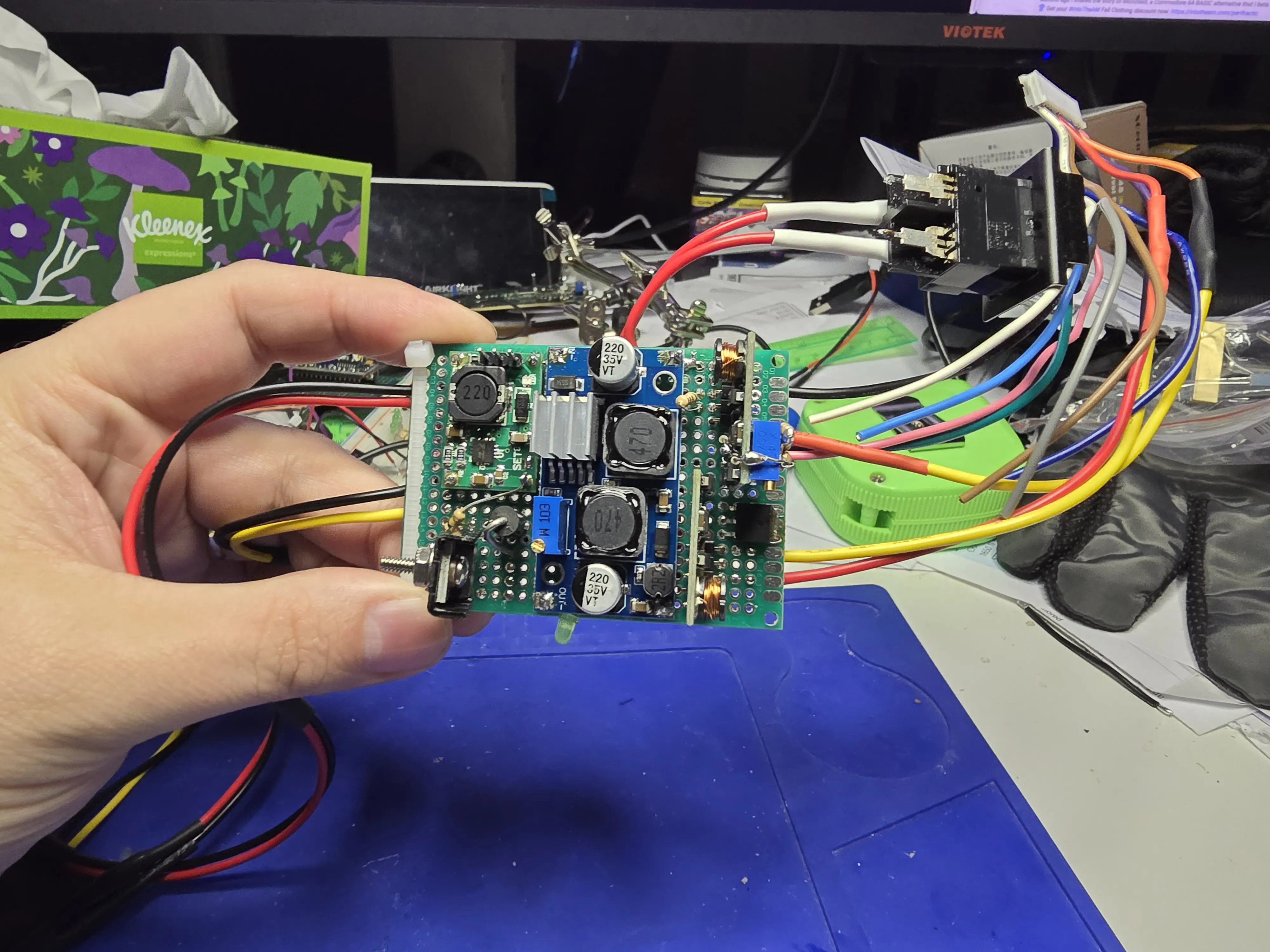
Handwired prototype board.
Which surprisingly worked!
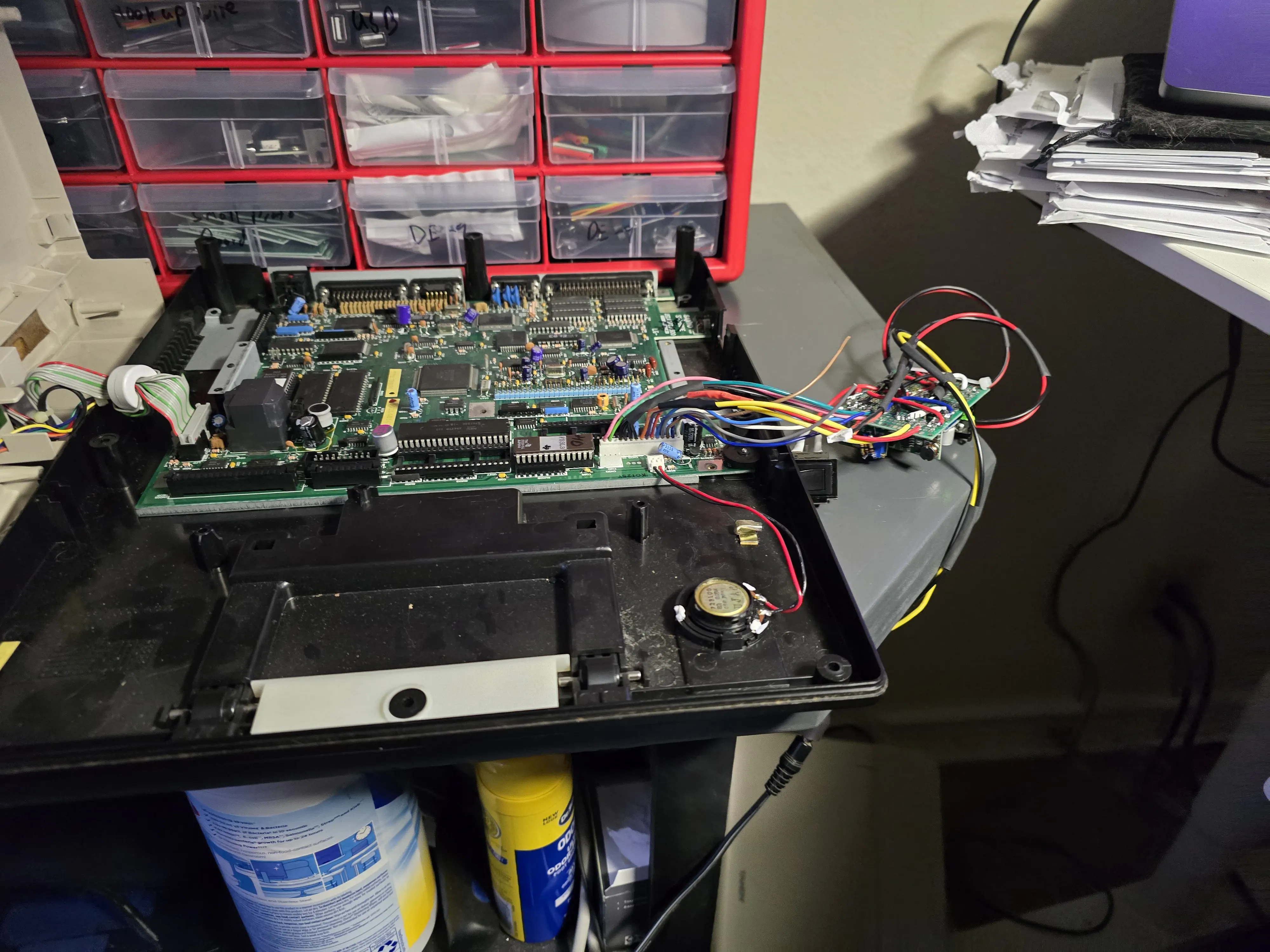
It works! PSU hook up with battery.
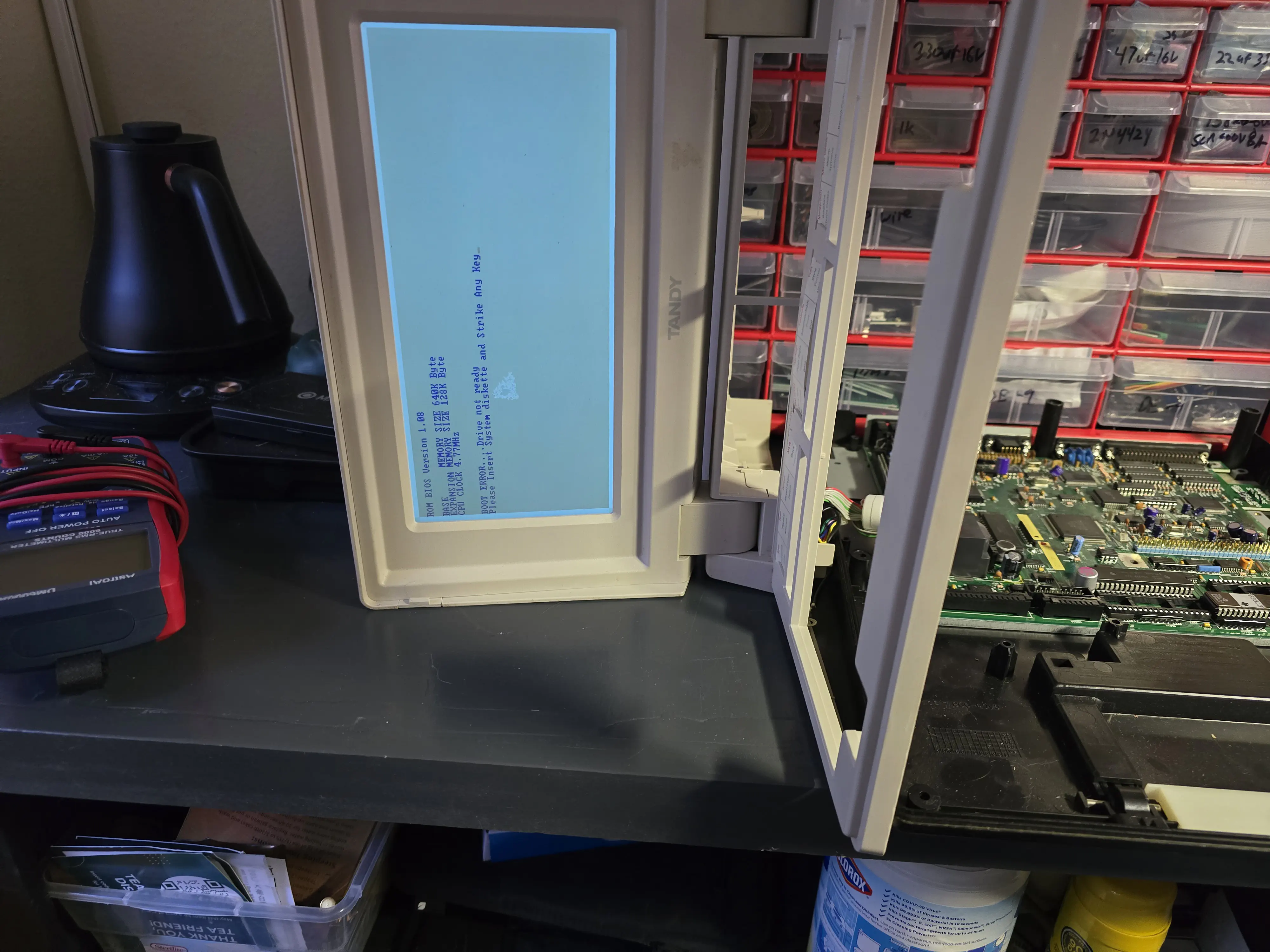
It works! Booted display.
I also hooked in a 5v rated Arduino Nano to experiment with the signal lines. That hasn’t been as successful as I’d like. The ADC on the Nano requires scaling because a 2s pack has a nominal voltage in the 7.4v and a max voltage around 8.2v or so. To get around this, I’ve used a voltage divider but that doesn’t give you a real idea of the charge left in the battery. Mostly, the Nano just convinces the machine to think it doesn’t have a low battery and is or isn’t running on wall power right now.
This gave me a possible replacement option, but a hand wired board like that wasn’t going to play nice in the original case to say the least. It also had issues with low input voltages causing the adjustable 5v converter to do nasty things like jump to 36v! There was also a problem where the machine would reboot if you had it running on battery power and plugged in the wall brick or the opposite. On top of that, the TP5100 module I was using for charging would sometimes just go boom and fail. So, this was not going to be something I felt comfortable installing even semi-permanently inside one of my machines.
Spelunking through Digikey and a bit of KiCad.
That led me to start a thread over on the VCF Forum asking about DC/DC converters and spending nearly a month digging through Digikey’s selection of parts. The problem I kept running into was the range of input voltages and the amount of current I needed as well as that danged -22v rail. The original wall supply would output 12v up to about 2.2A for the HD variant and 1.2A for the FD variant. Internally, I knew that the 12v rail had to be able to supply about an amp for the mechanical hard drive. I’m replacing that with an XT-IDE board from TexElec but it would be nice if anyone who wanted one of these could use it even with the original drives. I also wanted to stick with switching modules as much as possible for efficiency and because the raw input could be anywhere from about 5v to 12v.
No matter what I was looking at, I couldn’t come up with a trio of DC-DC converters that would work based on those parameters. I could usually find two of the four rails but not all of them and couldn’t really find a -22v converter, even adjustable, at all. So, I gave up looking for a -22v pre-build module and went with a custom boost converter based on the venerable MC34063. Since this rail was for LCD bias, it didn’t have to provide much in the way of current and could operate pretty easily on a range of potential input voltages. Plus there are a number of nice calculators out there you can drop numbers into and get the expected component values out of along with a rough circuit diagram for the configuration.
With that part out of the way, I made a call that I was going to put a boost converter on the front end of this circuit to push any input to a known intermediate voltage so I’d have a consistent jumping off point for all of the other rails. I picked 15v for that internal rails as it was just over the 12v that the original power brick supplied and I could easily find a 2A converter that would work from about 5v all the way to 12v on the input voltages. The MEZD41502A-C fit the bill nicely and, while not cheap, was not too expensive and almost exactly what I was looking for. (Note: I’m seeing that there may be a problem with sourcing that part now, the manufacturer and Digikey seem to disagree on if it’s still produced.)
So, the 15v boost converter let me bring all my input voltage up to a consistent range and significantly reduce the range of voltages that the other voltage converters had to support. Since I had to build the -22v rail by hand, that was just a matter of component selection. For the 5v rail, I found a nice 7805 replacement switching regulator with a TO-220 equivalent foot print. -12v proved a bit tricky but I found the N7812-1PH that could be configured as +12v or -12v module. Unfortunately, when configured in the +12v arrangement it needs 20~36v on the input making it not suitable for that rail. In fact, I had to give up on finding a switching regulator for the +12v rail and go with an LM340T-12 linear regulator instead.
That covered pretty much all of the rails I needed with enough current support for pretty much anything the machine could throw at it. Now it was time for a bit of KiCad and a circuit board.
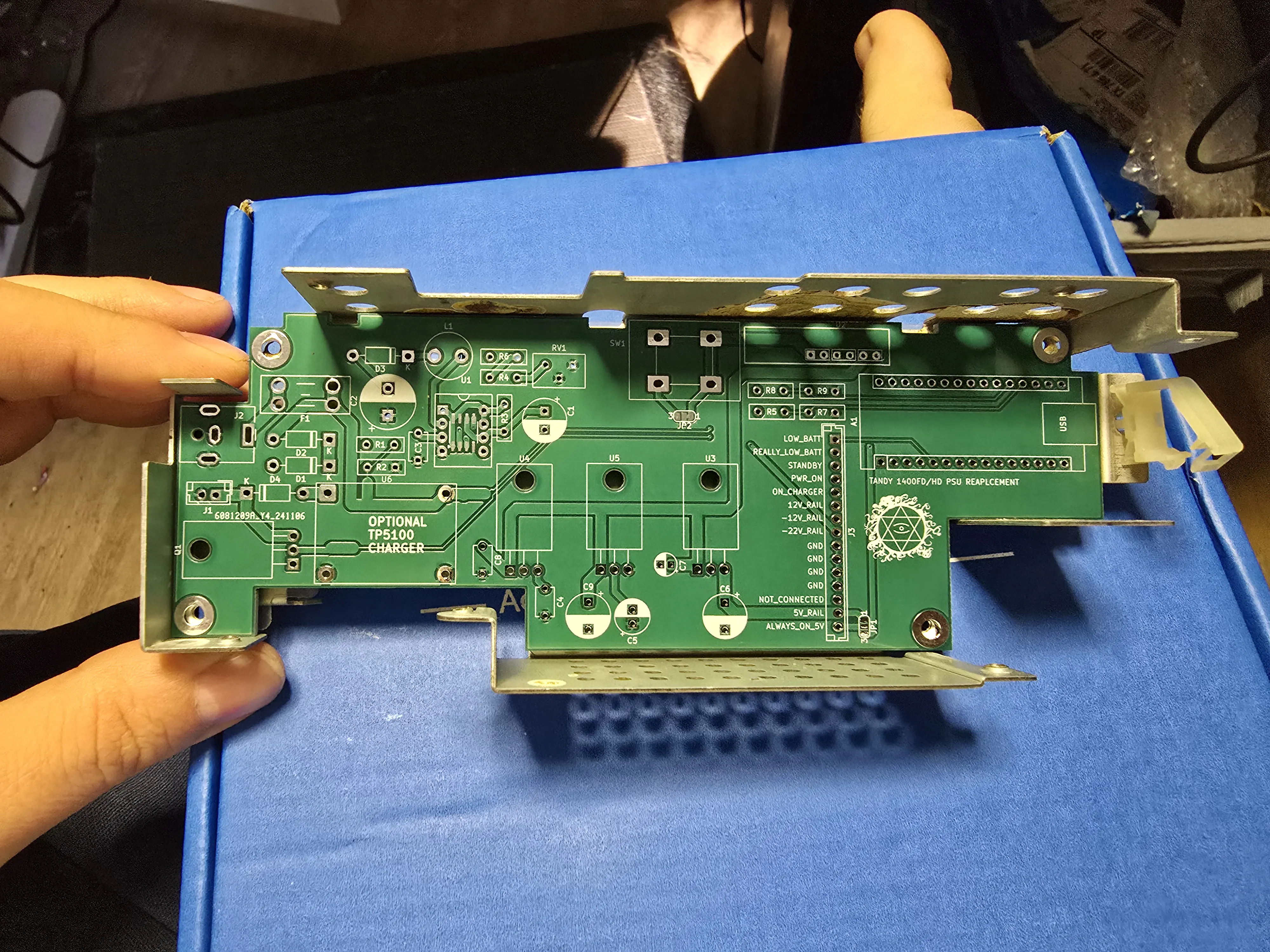
First PCB
To get the initial outline, I took a picture of the existing pcb and hand roughed out a drawing of the board in KiCad. Then I took a set of calipers and spent a couple of hours going feature by feature to get the outline just right. That was the most successful part of the layout thankfully. I’ve only had to tweak one of the mounting holes to get it to fit cleanly. The switch foot print and 15v converter foot print needed more tweaking to get them arranged just right and avoid the pins of on the back of the 15v converter to not touch the metal shield.
The first iteration took about a week to arrive and of course the -22v converter didn’t work right. Somehow, I’d mixed up the circuit diagram and had it half wired for a positive buck converter instead of a negative boost converter. Once I figured that out, I made a few other re-arrangements and sent off for a second set of boards. The four unused ones that would never work were turned into clocks.
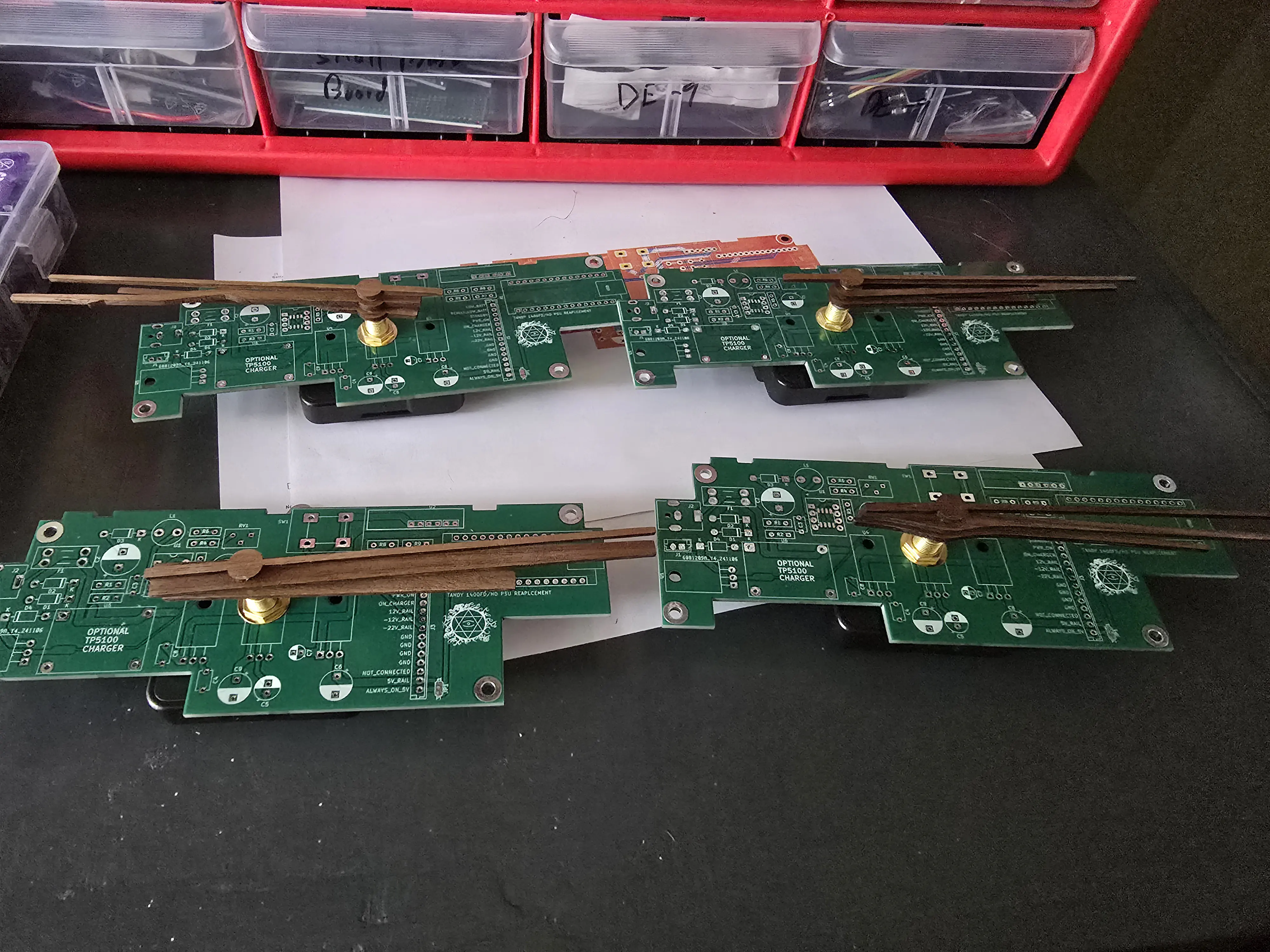
PCB clocks.
I’m holding onto the one I had started building to harvest parts and as a record of the various iterations this project has gone through.
Round Two
This time, I decided to spring for ENIG (gold plating) on the board and made a few adjustments that would allow usage of a harvested power switch from an original PSU. My select part was almost a perfect match, just a little shorter than the original. The two foot prints are just different enough that one won’t fit a board cut for the other. Thankfully widening one set of through holes allowed both to work. Unfortunately, I widened the wrong set and this round of board would have reversed the orientation of a stock power switch. That’s not really a problem, but it wouldn’t match the original. Also an easy fix.
When I was assembling this one, the -22v converted almost worked out of the box. I had the traces laid out correctly but had the feed back resistors setup wrong giving me -30v on the output instead of -22. Of course, that’s what the trimmer resistor was for, but I got values off by just enough that -22v wasn’t in the range of the trimmer. So, I had to tweak the fixed resistors a bit and I had a -22v rail without any material change to the board.
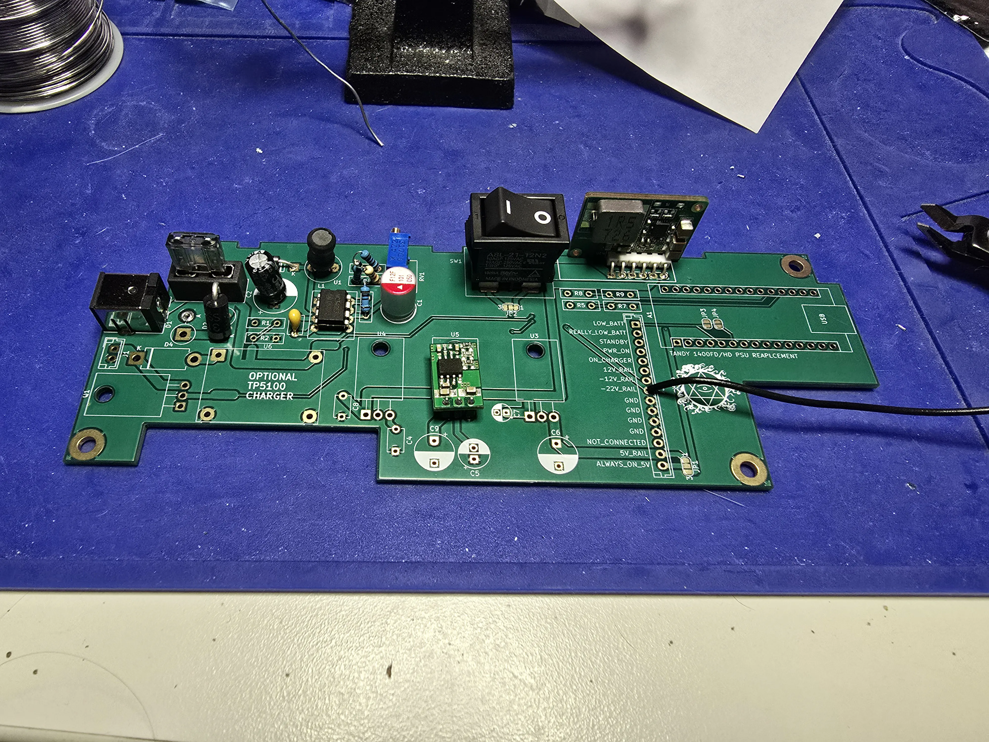
Working partially assembled PCB.
From there it was a matter of going part by part to add in the other components make a few minor notes to adjust the PCB for hole sizes and positioning and I had a functioning supply!
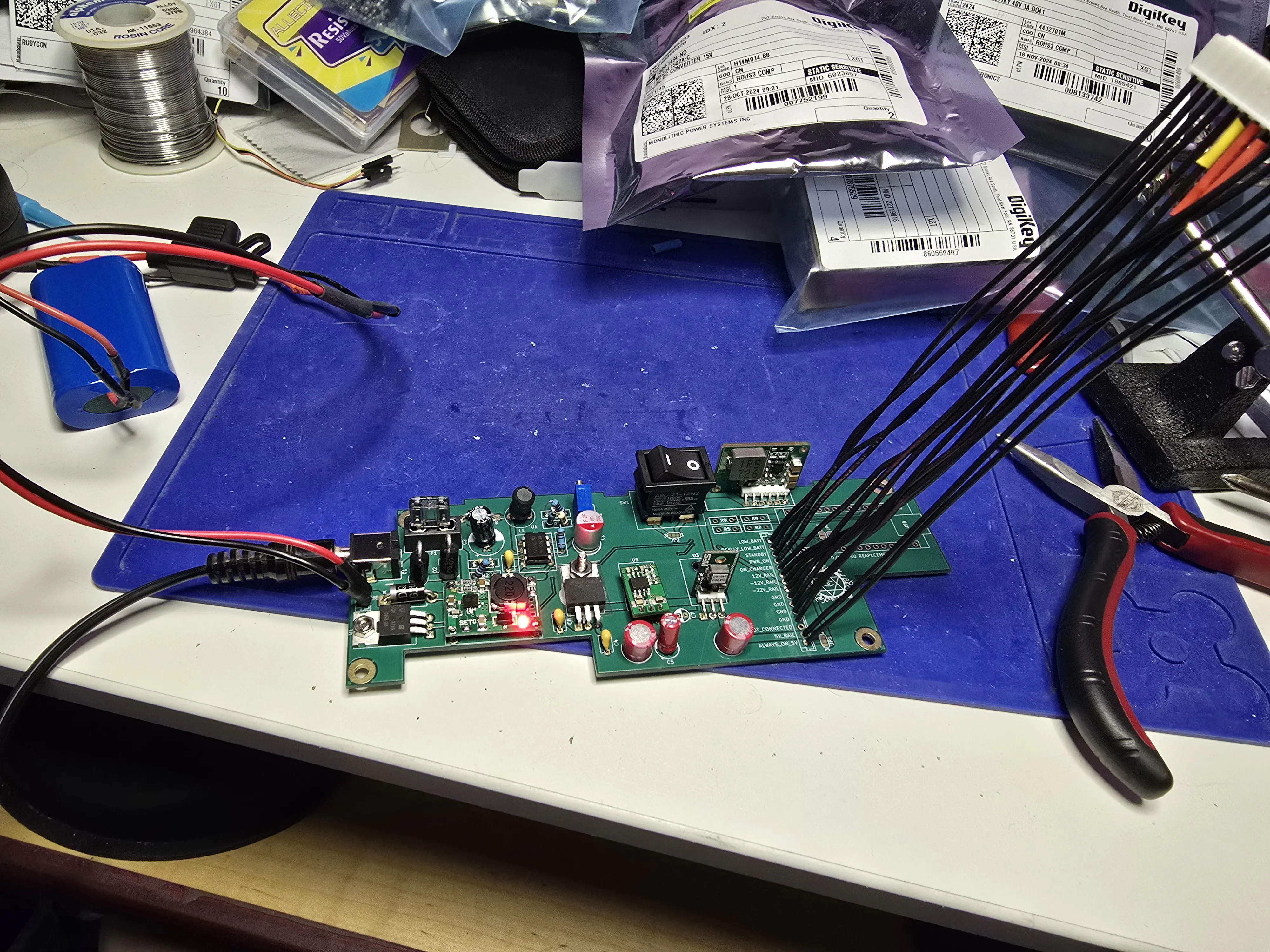
All voltage rails and a charger in line.
I tacked on the Arduino board and stole the battery leads off my original hand wired prototype to get a bootable machine!
Of course, it wouldn’t be quite that simple. The TP5100 module kept burning out when flipping the power switch and/or plugging in the external power supply. I probably burned out five or six of these boards and likely a couple more before finally realising what was going on. I documented the my research in this bug. Suffice it to say, the power switch was causing a voltage spike in the range of 22~24 volts, well above the absolute maximums of the TP5100 chip. There are supposed to be capacitors on the charger board for input filtering, but the cheapest bidder ceramics aren’t exactly the best at filtering that kind of pulse. I did a little experimentation with an oscilloscope a capacitor kit to find a value value sufficient to keep the spikes in under control. So far, taking on an extra 330uF has prevented the TP5100 from going nuts and smoking itself.
Incidentally, I discovered that the 0.1uF 50v capacitors in the Allecin Electrolytic Capacitor kit I picked up to have a range of values on hand are either mislabeled on polarity or just aren’t what they claim to be. I had two of the pop, loudly, when connecting the 12v supply. That really shouldn’t happen…
Whats Next
At this point, I have a third PCB design out to get boards made. If all goes well, I should have a set of them just after thanksgiving and be ready to build out the most recent iteration. I also have four spare boards that I could build out now that would work just great. I’m not sure about the charging circuitry just yet, I want to cycle that a bit more to see how it behaves. Li-ion batteries make me a bit nervous as they have a nasty habit of starting fires and I’m not sure how far I trust that TP5100 module.
The Arduino part of the board is also iffy. I had to use a simple voltage divider to avoid feeding the ADC to high a voltage and I’m pretty sure I have the ratio wrong. I did add jumpers to the board so it can be used without that part though. I might build out one unit in a wall power only configuration and use that for one of the other Tandy 1400s in my collection, not sure.
How Do I Get One?
Right now, you can take a look at the project over on Github. The full KiCad files, a parts list and a set of pre-built gerbers for the most recent board revision are right there in the repo. I suspect the current board will phantom drain a battery pack over the course of several days, but haven’t tested that. I you do want to build the charger enabled version, don’t leave it plugged into wall power unattended and don’t leave a pack in the machine indefinitely. I would probably suggest using the PSU in a wall power only configuration and relegating your machine to being a desktop like setup.
Until next time!